Balanced Line Impedance and Radiated Power
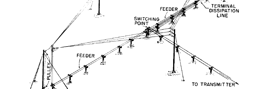
Build your own low-loss transmission line
Balanced two-wire transmission lines provide excellent low loss performance when they are used carefully. The loss can be an order of magnitude less than that of coaxial cable.
Twinlead is getting to be much less popular and commonly available now. For a long time its low loss at VHF and UHF frequencies made it the feedline of choice for television antennas. However, so many people are taking down their antennas, moving from terrestrial television reception to small satellite dishes and receivers or cable television, both of which connect via 75-ohm coaxial cable. Twinlead is made by embedding two copper conductors along either edge of a thin plastic strip, either solid flexible polyethylene or a thin polyethylene or polyvinyl chloride outer skin over polyethylene foam.
Then there is ladder line, sometimes purchased from a commercial source but often built by the home experimenter. This is simply a pair of wires with periodic insulating spacers. You just have to come up with a large number of these insulating spacers, of identical (or at least highly similar) dimension and small size, weight, and wind cross-section.
Amateur radio references through the early to middle 1900s described how to boil wooden dowel pieces in paraffin in order to permeate and coat the wood with wax. Ceramic pieces could be used, although they would be heavy, expensive, and difficult to impossible to cut to size and otherwise modify. A better material now would be plastic — narrow strips of thin plexiglass or other plastic.
Used food containers can provide plastic material, as can low-cost items like large plastic storage containers. However, a major problem is the degradation of plastic by ultraviolet radiation. Many common plastics used for food containers and other indoor uses quickly become brittle and break down when left outdoors and exposed to sunlight.
Consider using plastic objects intended for long-term exterior use, such as garbage cans. A large plastic outdoor garbage can could yield a large number of narrow insulating strips. Get those metal snips working!
Now, how long should those insulating spacers be?
The impedance of a balanced line is a function of the conductor diameter and spacing. A balanced line of two wires of diameter d spaced S center to center has impedance Z ohms, where:
Z = 276 log10(2S/d)
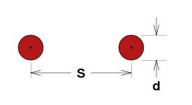
S = Spacing, center to center
d = Diameter of conductor
Notice two things. First, the units of measure don't matter (millimeters, inches, cubits) as long as you use the same units for both measurements.
Second, this is a simplified version of the equation assuming that S is much greater than d and that the spacers are small enough and far enough apart that we can ignore them and consider this to just be two parallel wires through an air dielectric.
You have to realize that the spacing will vary as the line flexes in the wind. If S is significantly larger that d, the impedance change will be relatively small. But if the wires are already close, inevitable small changes in the spacing will cause more significant impedance "bumps" or impedance variations along the line. That leads to increased loss and signal reflection. Practical ladder lines tend to have impedances of 600 to 1000 ohms.
Some power will be radiated from a balanced feedline. This is a loss of signal: A certain amount was fed into one end of the line, but only some of that comes out the other end, the rest being radiated along the length of the line. If the spacing is kept small relative to the wavelength, this radiation and loss can be kept to an acceptable level.
The power radiated from a balanced line carrying a signal at wavelength λ and an RF current of I amperes is Pr watts:
Again notice that the units of measure don't matter as long as S and λ are both in the same units.
Pr = 160 × I2 × (πS/λ)2
The RF current is a function of the input power and the line impedance. If the impedance is purely resistive and the input power is Pi watts:
P = I2 × R
I2 = P / R
Substituting for I2 and rearranging give us this:
Pr / Pi = ( 160 / Z ) × ( π S / λ )2
Or, to put it in more familiar terms, to express the ratio of the incidentally radiated power to the input power in decibels:
10 log10 ( Pr / Pi ) = 10 log10 ( (160/Z)×(πS/λ)2 )
Back to theKC9RG radio page