Data Cable Pinouts
EIDE / PATA / SATA / USB / Floppy
Data Cable Pinouts
This page describes data cable connectors and their pinouts. See the audio-video cable page for descriptions and pinouts for HDMI cables.
EIDE / PATA Cable Pinouts
What shall we call these devices....
In the beginning, or at least around 1986, was Western Digital's Integrated Drive Electronics (IDE) interface. That defined the low-level connection from a computer system board to a disk storage device. IDE refers to the disk controller being integrated into the drive and IDE providing an interface to a computer bus, initially the ISA bus. The host computer sees the storage device as an array of 512-byte blocks with a simple suite of interface commands.
CableWholesale.com has a nice archive of technical articles about cables, connectors, how to choose and use them, etc.
That led to AT Attachment and AT Attachment Packet Interface standards, so ATA/ATAPI is a complicated but accurate designation.
In 1994 Western Digital introduced Enhanced IDE (EIDE) or ATA-2 drives.
Roughly 2007-2009 Serial ATA or SATA largely replaced ATA/ATAPI technology on motherboards, leading to ATA being renamed PATA for Parallel ATA. SATA uses the same command set as PATA, but it uses high-speed serial cables moving data at 1.5, 3.0, and 6.0 Gbps.
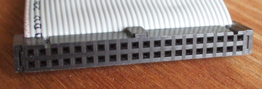
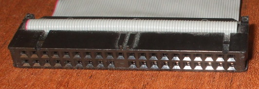
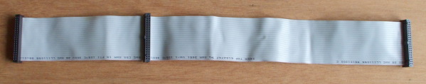
PATA cables and connectors.
The one at top is an old cable, a non-DMA cable with
just 40 conductors.
The one below is a newer DMA cable with twice as many
conductors, every other one of them grounded to reduce
cross talk.
Note the notches and bump forcing it to only be inserted
in the proper orientation.
Also notice that the DMA cable is solid where contact #20
would go, so it can only be plugged into interfaces
lacking that physical pin.
The contacts are numbered:
1 3 5 . . . 37 39
2 4 6 . . . 38 40
PATA Cable Pinouts
DD0 - DD15 — Data line 0 through 15.
IOCHRDY — I/O channel ready.
CS — Cable Select.
With the arrival of the Ultra DMA/33 mode, the cable went from 40-conductor to 80-conductor ribbon cable. The added 40 conductors are all ground lines, reducing crosstalk of the higher speed signals from what would have been adjacent conductors on 40-conductor cables.
Refer to the above picture and caption for the layout of PATA connectors. This table is rotated 90° from that table to fit into your display.
| 2 | GND | RST | 1 |
| 4 | DD8 | DD7 | 3 |
| 6 | DD9 | DD6 | 5 |
| 8 | DD10 | DD5 | 7 |
| 10 | DD11 | DD4 | 9 |
| 12 | DD12 | DD3 | 11 |
| 14 | DD13 | DD2 | 13 |
| 16 | DD14 | DD1 | 15 |
| 18 | DD15 | DD0 | 17 |
| 20 | VCC in | GND | 19 |
| 22 | GND | DDRQ | 21 |
| 24 | GND | I/O W | 23 |
| 26 | GND | I/O R | 25 |
| 28 | CS | IOCHRDY | 27 |
| 30 | GND | DDACK | 29 |
| 32 | N/C | IRQ | 31 |
| 34 | DMA66 detect | ADDR 1 | 33 |
| 36 | ADDR 2 | ADDR 0 | 35 |
| 38 | Chip select 3P | Chip select 1P | 37 |
| 40 | GND | Activity | 39 |
Pin 20 is usually not there, it may be a blank spot on the plug and missing a pin on the drive or motherboard connector to force plugging it in correctly oriented. But some flash drives use it to supply VCC to the drive.
Pin 28 is connected at the motherboard and master drive (far end) connectors, but not at the slave drive (middle) connector.
Pin 34 is connected normally (that is, to conductor #34) at the motherboard and slave drive connectors, but connected to ground within the motherboard connector.
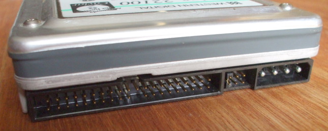
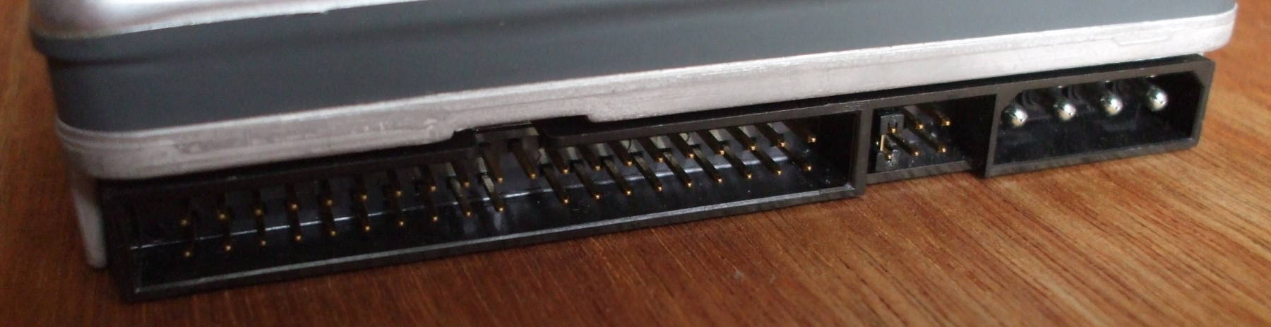
PATA disk drive. PATA data connector at left. Power connector at right. Six pins to add a jumper to select master versus slave device between them. Notice that pin 20 is missing. Also see the notch at top center in the black plastic shell to made with the bump on the connector, forcing correct orientation.
| Standard | Other names | Transfer modes (MB/sec) |
|
ATA-1
1994 |
ATA, IDE |
PIO 0, 1, 2 (3.3, 5.2, 8.3 MB/sec) |
|
Single-word DMA 0, 1, 2 (2.1, 4.2, 8.3 MB/sec) |
||
|
Multi-word DMA 0 (4.2 MB/sec) |
||
|
ATA-2
1996 |
Fast ATA, Ultra ATA, EIDE, Fast IDE |
PIO 3, 4 (11.1, 16.6 MB/sec) |
|
Multi-word DMA 1, 2 (13.3, 16.7 MB/sec |
||
|
ATA-3
1997 |
EIDE |
Like ATA-2 but without single-word DMA modes |
|
ATA/ATAPI-4
1998 |
ATA-4, Ultra ATA/33, UDMA/33 |
Ultra DMA 0, 1, 2 (16.7, 25.0, 33.3 MB/sec) |
|
ATA/ATAPI-5
2000 |
ATA-5, Ultra ATA/66, UDMA/66 |
Ultra DMA 3, 4 (44.4, 66.7 MB/sec) |
|
ATA/ATAPI-6
2002 |
ATA-6, Ultra ATA/100, UDMA/100 |
Ultra DMA 5 (100 MB/sec) |
|
ATA/ATAPI-7
2005 |
ATA-7, Ultra ATA/133, UDMA/133 |
Ultra DMA 6 (133 MB/sec) |
PATA data cable.
Left to right:
Master drive connector
Slave drive connector
Motherboard connector
PATA disks will have their data and power connectors on opposite ends. In between will be a set of jumper pins in which you can set the device to be the master or slave, or explicitly set it for "cable select", or leave off the jumper and allow it to use cable detection.
Cable select is the right choice for modern hardware. It may be marked as "CS" in a small diagram included on the label on the device case.
Now, as for how to set the jumper, refer to the documentation for your disk. There is no general rule. Ask Google the manufacturer name and model number to find out how to set the jumper.
As you see from this stack of three disks, the number of available jumper pins varies. The disk at top has six jumper pins, the one at middle has eight, and the one at bottom has ten.
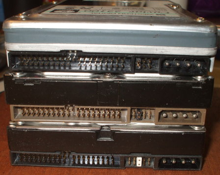
Three PATA disk drives with six, eight and ten jumper pins.
SATA Cable Pinouts
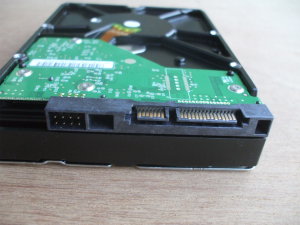
Disk drive with SATA data (center) and power (right) connectors.
SATA power connector
The contact areas on the pins are small, so multiple pins are ganged together for ground and the various voltages.
| Pin | 1 | 2 | 3 | 4 | 5 | 6 | 7 | 8 | 9 | 10 | 11 | 12 | 13 | 14 | 15 |
| Function | 3.3 V | Ground | 5 V | Ground | Staggered spinup | Ground | 12 V | ||||||||
SATA slimline power connector
Used for smaller devices, such as notebook drives.
| Pin | 1 | 2 | 3 | 4 | 5 | 6 |
| Function | Device present | 5 V | Diagostic | Ground | ||
SATA micro power connector
Used for 1.8-inch drives with SATA 2.6.
| Pin | 1 | 2 | 3 | 4 | 5 | 6 | 7 | 8 | 9 |
| Function | 3.3 V | Ground | 5 V | reserved | vendor specific | ||||
SATA data connector
| Pin | 1 | 2 | 3 | 4 | 5 | 6 | 7 | 8 |
| Function | Ground | A+ (Transmit) | A- (Transmit) | Ground | B- (Receive) | B+ (Receive) | Ground | coding notch |
First-generation SATA, now called SATA Revision 1.0 or SATA 1.5 Gbit/s, moves data at 1.5 Gbit/second. The data encoding overhead reduces the actual throughput to 1.2 Gbit/s.
SATA Revision 2.0 or SATA 3 Gbit/s doubles the data transfer rate and adds command queueing.
SATA Revision 3.0 or SATA 6 Gbit/s was specified in 2009. However, mechanical drives could barely saturate a SATA 3 Gbit/s link, so there was little market for SATA 6 Gbit/s until drive I/O speed increased significantly.
SATA Revision 3.1 was defined in 2011.
SATA Revision 3.2 increased the speed to 16 Gbit/s.
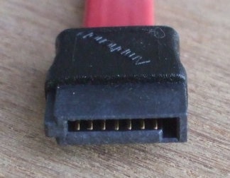
SATA data cable.
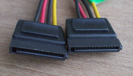
Two SATA power cables.
USB Cable Pinouts
These are laid out here as viewed looking into the plug:
Standard A
| Pin | 4 | 3 | 2 | 1 |
| Function | V- | Data+ | Data- | V+ |
Standard B
| Pin | 1 | 2 |
| Function | V+ | Data- |
| Function | V- | Data+ |
| Pin | 4 | 3 |
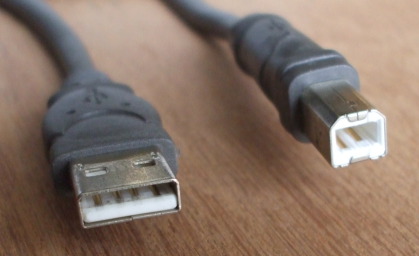
USB cable, Standard A connector at left and Standard B connector at right. The contacts are numbered as laid out in these tables.
Left to right:
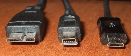
USB Micro-B for USB 3.0, USB Mini-B, and USB Micro-B for
USB 1.x/2.0 connectors.
Micro-B for USB 3.0 is shown with pins
10, 9, 8, 7, 6 left to right in the left half,
then 5, 4, 3, 2, 1 in the right half
Mini-B and Micro-B for USB 1.x/2.0 are shown with pins
1, 2, 3, 4, 5 left to right.
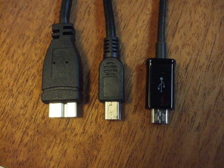
Left to right: USB Micro-B for USB 3.0, USB Mini-B, and USB Micro-B for USB 1.x/2.0 connectors.
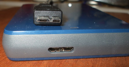
USB Micro-B connectors for USB 3.0 on a 1 TB external disk drive. Left-to-right are pins 10, 9, 8, 7, 6 in the left half, and 5, 4, 3, 2, 1 in the right half of each connector as seen here.
| Micro-B USB 3.0 Pinout | |
| Pin | Carries |
| 1 | Power (VBUS) |
| 2 | USB 2.0 differential pair D- |
| 3 | USB 2.0 differential pair D+ |
| 4 | USB OTG ID for identifying lines |
| 5 | Ground |
| 6 | USB 3.0 signal transmission line (-) |
| 7 | USB 3.0 signal transmission line (+) |
| 8 | Ground |
| 9 | USB 3.0 signal receiving line (-) |
| 10 | USB 3.0 signal receiving line (+) |
| USB 1.x/2.0 Mini/Micro Pinout | |
| Pin | Carries |
| 1 | +5 V power |
| 2 | Data - |
| 3 | Data + |
| 4 | host/slave detect |
| 5 | Ground |
| Version | Speed | |
| USB 1.x Low-Bandwidth 1996 |
1.5 Mbit/s | 192 kB/s |
| USB 1.x Full-speed 1996 |
12 Mbit/s | 1.5 MB/s |
| USB 2.0 Hi-speed 2000 |
480 Mbit/s | 60 MB/s |
| USB 3.0 SuperSpeed 2010 |
5 Gbit/s | 625 MB/s |
| USB 3.1 SuperSpeed+ 2013 |
10 Gbit/s | 1,250 MB/s |
Floppy Cable Pinouts
Yes, these are terribly archaic, but to be complete....
Drive A (at end of cable)
| 2 | Density 1=Low 0=High |
Ground | 1 |
| 4 | N/C | Ground | 3 |
| 6 | N/C | Ground | 5 |
| 8 | Index | Ground | 7 |
| 10 | Motor enable drive 0 | Ground | 9 |
| 12 | Drive select 1 | Ground | 11 |
| 14 | Drive select 0 | Ground | 13 |
| 16 | Motor enable drive 1 | Ground | 15 |
| 18 | Direct select | Ground | 17 |
| 20 | Head step | Ground | 19 |
| 22 | Write data | Ground | 21 |
| 24 | Floppy write enable | Ground | 23 |
| 26 | 0 = Track 00 | Ground | 25 |
| 28 | 0 = Write protect | Ground | 27 |
| 30 | Read data | Ground | 29 |
| 32 | 0 = Head select | Ground | 31 |
| 34 | 1 = Disk change 0 = Ready |
Ground | 33 |
Drive B (at middle of cable)
| 2 | Density 1=Low 0=High |
Ground | 1 |
| 4 | N/C | Ground | 3 |
| 6 | N/C | Ground | 5 |
| 8 | Index | Ground | 7 |
| 10 | Motor enable drive 1 | Ground | 9 |
| 12 | Drive select 0 | Ground | 11 |
| 14 | Drive select 1 | Ground | 13 |
| 16 | Motor enable drive 0 | Ground | 15 |
| 18 | Direct select | Ground | 17 |
| 20 | Head step | Ground | 19 |
| 22 | Write data | Ground | 21 |
| 24 | Floppy write enable | Ground | 23 |
| 26 | 0 = Track 00 | Ground | 25 |
| 28 | 0 = Write protect | Ground | 27 |
| 30 | Read data | Ground | 29 |
| 32 | 0 = Head select | Ground | 31 |
| 34 | 1 = Disk change 0 = Ready |
Ground | 33 |
Lines 9-16 are reversed.
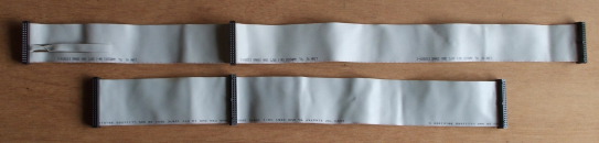
Floppy data cable above, and
PATA data cable below.
Notice that the PATA cable is limited to 18" total length,
and also notice the floppy cable's twist
between the Drive A and Drive B connectors.
Left to right on the floppy cable:
Drive A connector
Drive B connector
Motherboard connector
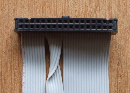
Floppy data cable connector, Drive A connector at the far
end, just beyond the twist of conductors 9-16.
Note the notches and bump forcing it to only be inserted
in the proper orientation. The contacts are numbered:
1 3 5 . . . 31 33
2 4 6 . . . 32 34