Building a 9:1 Unun HF Transformer
RF Transformers
I want to make a simple low-profile multi-band antenna
that's easy to put up and take down.
An end-fed half-wave antenna
has extremely high impedance.
It's sometimes called a "Zepp" because Zeppelins and other
dirigibles used end-fed wire antennas trailing behind them.
An end-fed random wire antenna
can present a more manageable impedance across several bands.
That is, if you're careful to choose a length that
isn't a multiple of a half a wavelength at a frequency
of interest.
So, we really need an end-fed not-so-random or perhaps
random-ish wire antenna!
A traditional compromise is an end-fed wire
84 feet (or 25.6 meters) long
covering all the amateur bands from
3.5 MHz up through the HF spectrum.
Or, 42 feet (or 12.8 meters) for 7 MHz
and higher.
The resulting antenna has varying impedance across the
amateur HF bands,
generally having significantly higher impedance than
the standard 50 Ω of coaxial feedline.
But not so extremely high as
a half-wave or multiple of that.
A 9:1 impedance transformer brings the varying but
generally high antenna impedance down to something
reasonably easy to match to 50 Ω.
The transformer approximately matches the unbalanced
coaxial feedline to the unbalanced
end-fed wire plus a short counterpoise.
Hence the name,
an unbalanced-to-unbalanced transformer,
an un-un or unun.
Here are my notes on
building a 9:1 unun transformer.

Autotransformer Circuit
Here's the circuit for a 3:1 autotransformer. There's just one winding in an autotransformer. One side uses the entire winding and the other side uses a segment of it. For this design, the antenna and counterpoise are connected to the ends, using the entire winding. The 50 Ω feedline uses one-third. The feedline shield connects to the end, along with the counterpoise (which is one or more wires, shorter than the antenna itself, so this isn't a dipole or doublet). The feedline center conductor connects one-third of the way up the overall inductor. The resulting 3:1 voltage transformation means a 9:1 impedance transformation.
The large black dots represent phasing, indicating the "hot" end of each of the three inductor segments. The "hot" and "cold" ends of the bottommost inductor are connected to the feedline center and shield, respectively.
So far I have simply drawn one inductor with three identical segments, along with some dots.

The feedline shield is shown above as being connected to ground. That's true at DC. At RF, however, there will be current flowing back down the exterior of the shield as well as out the counterpoise, and that point definitely will not be at RF ground. Not unless you actually connect it to an excellent ground, or have a counterpoise big enough to be an effective ground plane. But when you say "counterpoise" you generally mean something that's just an approximation or compromise.
Drawn this way I show it above, we don't really need those phasing dots to keep track of what's going on. But...
Here is that same circuit, rearranged.

The three inductor sections will be wound in parallel on a toroid core, then connected in series. This drawing is a much better approximation to how the wire is laid out.
Three separate windings will each extend most of the way around the toroid, from about 7 o'clock up around the top and down to 4 o'clock. The left end of each segment in the above could be at 7 o'clock, and the right end (with the black dot) at 4 o'clock. We need to connect the right (dotted) end of the bottom winding to the left (undotted) end of the middle one, and the right (dotted) end of the middle one to the left (undotted) end of the top one.
Toroid Inductance and Reactance
I will build the transformer on a toroidal core. An inductor on a toroid is self-shielding, and the iron-powder or ferrite core material has much higher permeability than air. That means much higher magnetic flux within the coil, and that means far more inductance per turn. Inductance scales linearly with permeability, and as the square of the number of turns.
AL is the inductance index for a toroidal core. Be careful, these are specified in different units! As a general rule, for powdered iron cores designated T-xx-yy, they are usually in units of microhenrys per 100 turns, and for ferrite cores designated FT-xx-yy, they are usually in units of millihenrys per 1000 turns. Make sure you know how the manufacturer specified AL for your cores. Otherwise your result will be off by a factor of 10.
I'm using MathJax to do math within HTML.
The core material has much higher permeability than air. This greatly increases the magnetic flux density, and with it, the inductance. Exactly how much depends on the characteristics of the material and the cross-section area.
For a powdered iron T-xx-yy toroid, with AL specified in "μH per 100 turns", the inductance of an N-turn inductor is, in μH: $$ \begin{aligned} L_{ \mu H } &= A_L \left(\frac{N}{100}\right)^2 \\ &= A_L \frac{N^2}{10,000} \end{aligned} $$
For a ferrite FT-xx-yy toroid, with AL specified in "mH per 1,000 turns", the inductance of an N-turn inductor is, in mH: $$ \begin{aligned} L_{ mH } &= A_L \left(\frac{N}{1,000}\right)^2 \\ &= A_L \frac{N^2}{1,000,000} \end{aligned} $$ Or, in μH: $$ L_{ \mu H } = A_L \frac{N^2}{1,000} $$
You calculate an inductor's reactance XL or impedance ZLas: $$ X_L = 2 \pi f L \ Ω $$ $$ Z_L = j 2 \pi f L \ Ω $$
where:
\( f \) = frequency in Hz
\( L \) = inductance in Henrys
And since multiplying by one million cancels out
dividing by one million, we could instead use
units of megahertz and microhenry:
\( f \) = frequency in MHz
\( L \) = inductance in μH
Selecting the Toroid
This design, my first attempt at a broadband 9:1 transformer, is just a prototype.
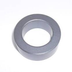
I used an FT-140-43 toroid.
FT means ferrite material, versus T for an iron-powder toroid. That means higher permeability, much higher inductance per turn, limited to use at lower frequencies.
140 means 1.40 inches outer diameter. Large enough to take several turns of wire without needing to use small-diameter magnet wire.
43 specifies the ferrite material. Manufacturers such as Amidon and Fair-Rite agree on what the numbers mean, but they're like catalog numbers. You need to look up characteristics in a table. Material #43 is a nickel-zinc ferrite, NiZn for short but actually NiaZn(1-a)Fe2O4.
The specifications at Fair-Rite and Amidon describe their various mixes. The #43 material straddles the boundary for use at HF. Fair-Rite describes it as most suitable for use as an RF inductor at 10 MHz and lower, and then for use for suppressing signals from 25 to 300 MHz. Amidon says it's for suppressing signals from 20 to 250 MHz. So, for the amateur bands at 14, 18.1, and 21 MHz it will become gradually more and more lossy. For the 24.9 and 28 MHz bands it will be less suitable yet.
The #61 material would probably be a better choice. Amidon describes #61 as useful for low-loss RF inductors up to 25 MHz, then for EMI/RFI suppression above 200 MHz. It has lower permeability than the #43 material, 125 rather than 850. So, it requires significantly more turns to have the same inductance. However, if I were interested in 160-meter and 80-meter operation, down at 1.8 and 3.5 MHz, the #61 material would become less practical due to the number of turns required.
Winding the Toroid
One design rule of thumb is:
The impedance of the smaller winding of an RF transformer should be at least 4 to 5 times the lower impedance, at the lowest frequency.
The 50 Ω feedline is the lower impedance. So, at least 250 Ω impedance to be safe. $$ X_L = 2 \pi f L \ Ω $$ And so, for 250 Ω at 3.5 MHz: $$ \begin{aligned} L_{ \mu H } &= \frac{ X_L }{ 2 \pi f_{MHz} } \\ &= \frac{ 250 }{ 2 \times \pi \times 3.5 } \\ &= 11.4 \mu H \end{aligned} $$
My FT-140-43 ferrite toroid has an AL of 885 mH/1000 turns. $$ \begin{aligned} L_{ \mu H } &= A_L \frac{ N^2 }{ 1,000 } \\ &= 885 \times \frac{ N^2 }{ 1,000 } \\ &= 0.885 \times N^2 \end{aligned} $$ and so: $$ \begin{aligned} N &= \sqrt{\frac{ L_{ \mu H } }{ 0.885 }} \\ &= \sqrt{\frac{11.4}{0.885}} \\ &= 3.6 \end{aligned} $$ Therefore, at least 11.4 μH created with at least 4 turns.
I doubled the number of turns. Eight turns yields 56.6 μH inductance which means 1,245 Ω impedance at 3.5 MHz.
Time to wind a toroid!
First I used some yarn to estimate how long a piece of wire was needed for an 8-turn coil on this core. You count the number of passes through the center. Count them in this picture, you should see 8.

I left the yarn a little loose, and added another 10–20% to that length.
I had some insulated #18 wire. 18 AWG is 0.75 mm2.
Better yet, I had three spools of wire with insulation in three different colors. That would make later steps easier!
I started with the red, planning for this to be the primary segment to which the feedline connected. It happened that my red wire had noticably thicker insulation, so I figured it would be best to start with that. Get the thickest and stiffest winding on first.

The length had worked out well, so I cut a piece of the black wire of the same length. I wound it in the same direction or sense. With just two wires, they filled approximately 75% of the core and laid side-by-side around both the inside and outside perimeters.

The last color is yellow. The three segments can lie side-by-side around the outer perimeter, but there has to be some overlap around the interior.

You work the wire into place with your fingers to get the windings tight to the core and aligned the way you want. But the insulation is stiff and the windings won't stay in place. So, I used two small wire ties.

Mounting the Transformer
I built the transformer into a plastic box used for exterior electrical power. Don't use a metal enclosure!
First, I used a step drill on the blank cover, and mounted a BNC panel connector and two binding posts which also accept banana plugs.


Then I attached the transformer. In the following table of connections the "hot" end of each segment is closer to the antenna, indicated with a dot in the circuit diagrams above.
| Segment | Color | "Cold" end | "Hot" end |
| 1 | red | BNC shell and black binding post | BNC center |
| 2 | black | BNC center | "cold" end of segment 3 |
| 3 | yellow | "hot" end of segment 2 | red binding post |


It's all assembled and ready for testing!

NanoVNA
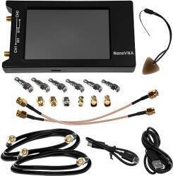
NanoVNAI had recently purchased a NanoVNA, a hand-held vector network analyzer that covers 50 kHz through 1,300 MHz. All of HF plus VHF and UHF through the 23 cm or 1296 MHz amateur band. Here's an application for it.
It comes with two short cables with SMA connectors, an SMA barrel adapter, and three terminators — open, short, and 50 Ω. Plus two USB cables to connect it for charging, and possibly use with a smartphone app. And, with some kits, much more.
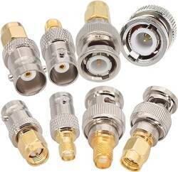
In the same order I bought a set of SMA–BNC adaptors with all gender combinations.
SWR Measurements
I had built a 9:1 transformer, so I put a 470 Ω resistor across the binding posts. Then I connected the S11 port, labeled CH0, to the transformer, and put the 50 Ω terminator on the S21 or CH1 port.
I set the VNA to sweep from 50 kHz to 30 MHz and display SWR or standing-wave ratio — how much energy is reflected back due to impedance mismatch? 1:1 would indicate a perfect match. The marker moves in discrete steps, so we see the SWR is 1:1.04 toward the bottom of the 3.5 MHz band.

At 7.238 MHz, toward the top end of the 40-meter band, it's still down at 1:1.04.

It has increased a little by the time we reach the middle of the 20-meter band. It's 1:1.20 at 14.1265 MHz.

At 21.015 MHz, the bottom of the 15-meter band, it has only increased to 1:1.54. Of course that is the impedance mismatch, it is probably starting to become significantly lossy.

Up in the 10-meter band, where I don't plan to use it, the SWR is still low. 1:2.14 at 28.203 MHz.

Resistance Measurements
Now let's see what the resistance and reactance is across the HF spectrum. Resistance first.
51.2 Ω at 3.644 MHz.

46.7 Ω at 14.126 MHz.

Climbing slightly to 52.9 Ω at 24.9085 MHz.

Then increasing to 63.1 Ω at 28.5025 MHz.

Reactance Measurements
Now for the reactance. An impossibly ideal transformer would have zero reactance. But as long as it's a small fraction of the 50 Ω resistance, it's good.
Reactance was just 2.05 Ω at 3.644 MHz.

2.37 Ω at 7.238 MHz.

8.40 Ω at 14.1265 MHz.

It climbs more steeply as frequency increases. It's at 21.1 Ω at 21.014 MHz.

Then 42.3 Ω at 28.203 MHz, approaching the resistance.

Smith Chart Measurements
The NanoVNA can draw you a Smith chart. With the 470 Ω load, it's closest to the ideal 50 + j0 Ω at 7.875 MHz. 49.5 Ω and 53.8 nH.

By 21.150 MHz the reactance has climbed to 48.2 Ω and 162 hH.

Now it's time to cut and hang a wire and see what this can do!
