Build a Simple TV Antenna
Receive Local to Regional Signals
Compromise Broadband Antenna Design
Broadcast television in North America occupies three radio frequency bands: VHF low from 54 to 88 (channels 2-6), VHF high from 174 to 216 MHz (channels 7-13), and UHF from 470 to 698 MHz (channels 14-51, channels 52-69 or 698-806 MHz have remained in limited use by some low-power stations). The range from 54 to 698 MHz covers between three and four octaves. Any general "television antenna", even an enormous log-periodic beam, will be a compromise.
Before the digital transition, a TV channel was simply the numerical designation of its 6 MHz wide range of frequency. A digital broadcast signal is a data stream that includes metadata like the virtual channel number or other identification.
WLFI, the local TV station where I live, broadcast on UHF channel 18 from 1957 until the digital transition in June 2009. People were accustomed to be being "Channel 18". It now broadcasts on 198-204 MHz, physical channel 11, but it identifies as channel 18. "WLFI, TV-18"
A new low-power station WPBI started broadcasting in late 2016, on both physical and virtual channel 16, at 482-488 MHz.
Building an Antenna for VHF Channel 11 and UHF Channel 16

Amazon B06XZ31W3M
The Single-Bay Gray-Hoverman antenna definitely is a compromise, trading size against performance to yield a small size that can easily be used indoors or in an attic. Several web pages have SBGH plans, a good example is here.
It worked about as well as could be expected of such a compromise. I live in a masonry building with some steel reinforcement, it's an effective shield keeping radio signals out. The sliding glass door out onto my balcony faces toward about 20°, putting both transmitters about 90° off to the right and shielded by the building. The SBGH antenna had to sit out on the balcony to receive the two stations, where it mostly captures signals scattered from nearby buildings.
I next built a pair of folded dipoles sized for the two center frequencies of 201 and 485 MHz. I used the same #12 insulated house wire that I had used for the SBGH.
A single folded dipole has an impedance of about 300Ω. As for two of them, I was hoping that the impedance would be reasonably close to 300Ω at each dipole's resonant frequency. I used a 300Ω:75Ω balun at the feedpoint, connecting to a length of RG-59 with F connectors.
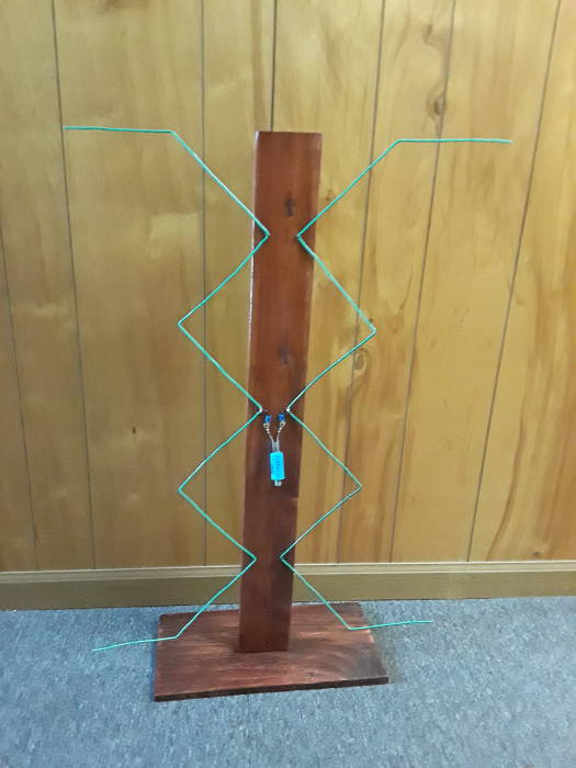
The Single Bay Gray Hoverman (or SBGH) antenna.
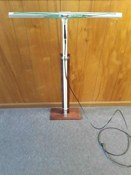
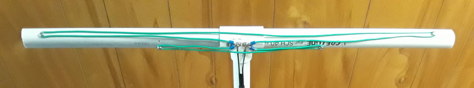
Dual folded dipole television antenna.
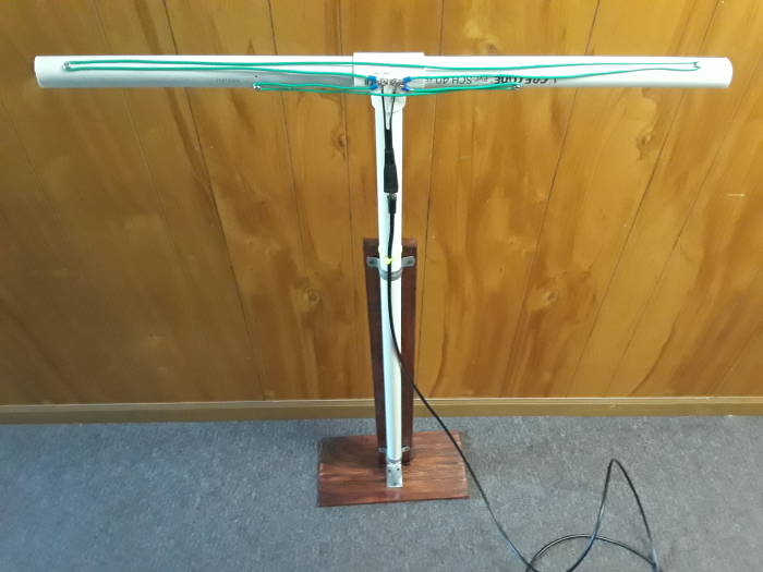
I used 1" PVC pipe for the frame, drilling and then screwing in small sheet metal screws to serve as the feedpoint and the dipole end supports.
Wavelength in meters is 300 divided by frequency in MHz: $$ \begin{aligned} {\lambda}_{meters} &= 300 / f_{MHz} \\ {\lambda}_{mm} &= 300 / f_{GHz} \end{aligned} $$
North American television frequenciesA dipole is λ/2, and I used 95% of that to account for the dielectric effect of the air plus the insulation. Plus the nearby PVC pipe, plus whatever other approximations might be appropriate in this rough design. That works out to dipole lengths of 70.9 and 29.4 cm for North American channels 11 and 16.
The Result?
My dual folded dipole outperformed the Single-Bay Gray-Hoverman antenna. Given the all-or-nothing reception of a digital TV signal, I can't make very meaningful comparisons based just on what it receives and how the resulting picture looks. But, with the dual dipole sitting in the same location on a desk near the window, the TV receives both stations, meaning five digital streams from one and two from the other. With the SBGH design, it receives just one station.
nanovna-saverHere are the results for the dual folded dipole as captured and saved with the nanovna-saver package. Sweeping 150–550 MHz in 400 segments, red and green markers at nominal 201 and 485 MHz, respectively. The VSWR and S11 return loss seem quite good for 485 MHz, and are acceptable for 201 MHz.
| Frequency: | 201.0 MHz |
| Impedance: | 30.3 + j21.0 Ω |
| Series L: | 16.62 nH |
| Series C: | -37.725 pF |
| Parallel R: | 44.814 Ω |
| Parallel X: | 51.141 nH |
| VSWR: | 2.065:1 |
| Return loss: | -9.182 dB |
| Frequency: | 485.0 MHz |
| Impedance: | 43.5 + j4.77 Ω |
| Series L: | 1.5665 nH |
| Series C: | -68.743 pF |
| Parallel R: | 43.98 Ω |
| Parallel X: | 131.38 nH |
| VSWR: | 1.190:1 |
| Return loss: | -21.253 dB |


