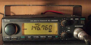
Modifications for the IC-3220 VHF/UHF FM Transceiver
The IC-3220 VHF/UHF FM Transceiver
I bought mine used at the Dayton Hamfest in 2007, and its manual was printed in 1990. Definitely not the state of the art, although that sort of thing intrigues me...
There were three variants of the IC-3220. I believe that these are the distinctions:
- IC-3220A — US & Asia (Japan) model — includes CTCSS/PL subaudible tone encoder and DTMF tones with the HM-56 microphone.
- IC-3220E — European model — includes 1750 Hz tone call, has slightly different default receive coverage.
- IC-3220H — Seems to be like the IC-3220A with higher transmit power.
| IC-3220A/E | IC-3220H | ||||
| Power | Current | Power | Current | ||
| VHF | High | 25 W | 7.0 A | 45 W | 10.0 A |
| Low-2 | 10 W | 4.5 A | 10 W | 5.0 A | |
| Low-1 | 1 W | 2.5 A | 5 W | 4.0 A | |
| UHF | High | 25 W | 8.0 A | 35 W | 10.0 A |
| Low-2 | 10 W | 5.0 A | 10 W | 6.0 A | |
| Low-1 | 1 W | 3.0 A | 5 W | 4.5 A | |
Extended Receive Coverage
Unfortunately, this requires hardware modification rather than a firmware power-on reset as on some other Icom gear.
[1] Get a service manual
Ask Google something like the following:
[2] Expanding VHF receive coverage
Expanded VHF receive coverage:
118.000 - 135.995 MHz AM
136.000 - 174.000 MHz FM
The AM demodulation seems to be done by slope detection,
and it is not very sensitive.
The IC-2SAT handheld (of similar vintage) seems to
be more sensitive in the aviation band than either
the IC-3220 or the IC-229 mobiles.
To extend VHF receive coverage:
Cut D6 on the Logic board
(located at the front of the radio).
[3] Expanding UHF receive coverage
Expanded UHF receive coverage:
400.000 - 479.000 MHz FM
Sensitivity outside the ham FM band of 430-450 MHz
is noticeably worse, see the tables below.
To extend UHF receive coverage:
Cut D4 on the Logic board
(located at the front of the radio).
[4] Further Notes on extending frequency coverage
Note that the two referenced pages slightly contradict each other, and one contradicts my experience.
This wells.com page
says that you must cut both D6 and D4 for VHF,
and D5 for UHF, and also push and hold
[V/MHz], MONI], and
[Mic-DN] while turning on the power.
I did not have to do that —
cutting D6 gave full 118.0-174.0 MHz receive and
cutting D4 gave 400.0-479.0 MHz receive,
without any button-down power-up.
Also, this quellidellaradio.it page says that you can extend transmitter range on VHF to 136.0-174.0 MHz by soldering a bridge between the solder pads next to D9, and on UHF to 400.0-479.0 by installing a 1SS190 diode at D9. The wells.com page says that you must install a 1SS181 diode at D9 and solder between lands A and B to extend both VHF and UHF transmit frequencies. I think they're describing the same two changes using nearly identical diodes. Compare the diode datasheets to be certain.
Receive Sensitivity
As measured with an HP 8656B signal generator. Signal levels were set in integer dBm. That means that the microvolt levels are quantized the way you see here.
| Frequency | Signal level | ||||||
| Decent SNR on AM | FM full-quieting | Solid copy but noisy | Breaks squelch | S9 on meter | S5 on meter | S1 on meter | |
| 118-123 MHz | 5.0 μV | ||||||
| 125 MHz | 2.5 μV | ||||||
| 130 MHz | 1.5 μV | ||||||
| 132-135 MHz | 1.25 μV | ||||||
| 135.995 MHz | 0.5 μV | ||||||
| 136-162 MHz | 0.5 μV | 0.25 μV | 0.1 μV | ||||
| 162-174 MHz | 0.25 μV | ||||||
| 400 MHz | 5.0 μV | 2.0 μV | 0.4 μV | 15.8 μV | 10.0 μV | 5.62 μV | |
| 410 MHz | 5.0 μV | 2.0 μV | 0.4 μV | 22.4 μV | 14.1 μV | 7.94 μV | |
| 420 MHz | 5.0 μV | 2.0 μV | 0.4 μV | 31.6 μV | 20.0 μV | 12.6 μV | |
| 430 MHz | 5.0 μV | 2.0 μV | 0.4 μV | 56.2 μV | 35.5 μV | 20.0 μV | |
| 440 MHz | 0.8 μV | 0.3 μV | 0.1 μV | 6.31 μV | 3.98 μV | 2.24 μV | |
| 450 MHz | 0.8 μV | 0.3 μV | 0.1 μV | 3.98 μV | 2.82 μV | 1.58 μV | |
| 460 MHz | 5.0 μV | 2.0 μV | 0.4 μV | 70.8 μV | 50.1 μV | 28.2 μV | |
| 470 MHz | 5.0 μV | 2.0 μV | 0.4 μV | 70.8 μV | 44.7 μV | 25.1 μV | |
| 479 MHz | 5.0 μV | 2.0 μV | 0.4 μV | 56.2 μV | 39.8 μV | 22.4 μV | |