3-D Range Sensor Design
3-D Data Collection, Analysis, and Applications — Sensor Design
Click here for a muchmore up to date version
The sensors used in this work are single-plane structured-light range sensors. A light projector (P in the below graphic) illuminates the scene with a plane of light. A camera (C in the graphic) views the intersection of the light plane with the scene from a vantage point outside the plane of light. The resulting image contains a collection of illuminated stripe segments.
Each illuminated region seen by the camera is a sequence of one or more points in (row,column) image space. It's fairly obvious that the general shape of the lighted regions in the image reveals the general 3-D shape of the illuminated objects.
What's not so obvious is that if you know the optics of your projector and camera, and their relative geometry, the (row,column) position of an illuminated point uniquely defines the actual (x,y,z) position of that point. For details on the sensor design and excellent description of how to calibrate it, see "Modeling and Calibration of a Structured Light Scanner for 3-D Robot Vision," by Chien-Huei Chen and Avi C. Kak, in the Proceedings of the IEEE International Conference on Robotics and Automation, pp. 807-815, Raleigh NC, March 1987.
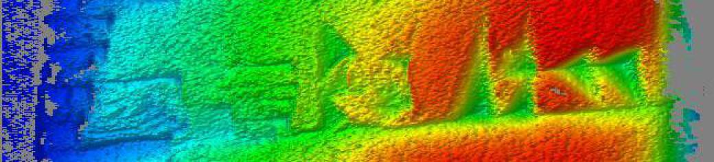
Granted, that sensor is really a 2-D sensor — it only measures within the light plane. Well, all you have to do is translate the sensor (or the target) to collect a series of images of light stripes, corresponding to a collection of 2-D slices of the scene. You can even accumulate the individual stripes to form an image we call a ``composite light-stripe image'' — it doesn't really provide any precise measurement, but it really helps you to visualize the process. Click here to see just one composite light-stripe image of a fish skull. Or, if you have lots of bandwidth and/or patience, click here to see a large collection of large composite light-stripe images, showing how various parameters can be tuned. 5.6 megabytes, you have been warned!
As for the spatial sampling rates possible with such a scanner, it depends on the optics of the camera and the relative geometry of the camera, light stripe, and the target. A simple approximation is that if your camera and video digitizer produce images of dimension 512 by 485 pixels, then divide the dimensions of the area that is the intersection of the camera's field of view with the light stripe by about half those number, or by approximately 250 in this case. For more details on calibrating sensors and calculating the resolution, see a copy of an e-mail message I sent to the lab group.
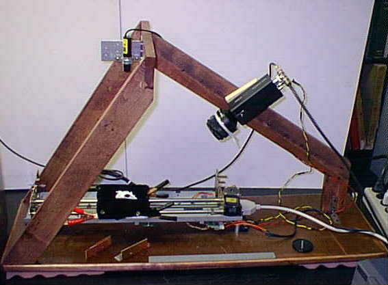
Here is a picture of a simple structured-light sensor. While this sensor may look rather crude, it is capable of capturing range data with a spatial sampling rate of about 20 microns. The light source is the small black cylinder with the yellow sticker mounted at the highest point. The camera is a North Country monochrome CCD camera. The movable target stage is — no joke — built from a dot-matrix line printer head carriage assemply. The large electrical clips are simply holding a piece of black velvet on the stage itself.
Here is the data from this new design