Scanning X-Ray Films
Building a Proper Back-Light Illumination Source
In the previous stage, we modified a flatbed scanner to disable its internal light. X-ray films have to be illuminated by transmission, not reflectance. The development process can create some unusual metallic tinged patterns in the fully exposed and saturated regions of films. That is, the blackest areas.
These areas of metallic sheen are only visible due to the light they reflect, they seem to cause little to no change in transmitted light.
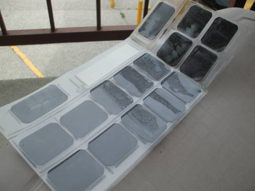
Some films and plastic carrier sleeves react somewhat over time, see those in the middle section in the first example below. While this looks ominous, these films looked much better than you would expect when viewed on a light box.
The four films in the second example below are more typical. They have been photographed on a light box.
It is tempting to consider simply photographing films placed on a light box. This was attempted, but it did not work for reasons related to the problems experienced with the scanner. More on that later....
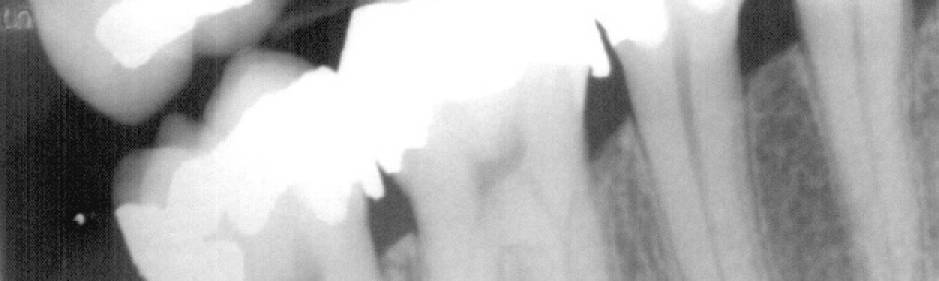
This full mouth series of X-ray films has reacted with the plastic carrier sleeve.
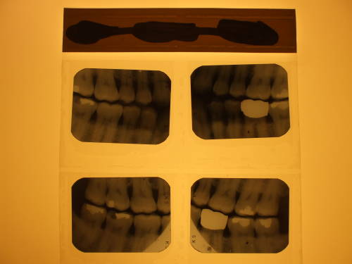
A sleeve of four films on a backlit viewer. A white paper or plastic strip across the top of the sleeve is used to record the patient's name and date. All have been completely obscured in these images.
I needed some type of light box. An ideal light box would have an illuminated area the same size as the scanner's glass plate, it would have very even and carefully controlled brightness, it would be easy to use, and it would be of low cost. A practical design will have to partially meet all these requirements with some acceptable balance...
Someone at the School of Electrical and Computer Engineering at Purdue University was throwing away a perfectly good steel equipment case! Black wrinkle-finish paint, made from steel rather than aluminum, this is a World War II vintage case. The opposite side panel is stamped CS-48, dating it to the early 1940s at least. See, for example, this radioblvd.com page on WWII and early post-WWII radio gear showing "Four BC-375 Tuning Units mounted in their CS-48 containers on the wall." The BC-375 transmitter design dates from 1935, the CS-48 case was sometimes used for mounting its associated antenna tuner among many other applications.
This would serve as an excellent starting point for this project!
Its all black interior was a problem. If I filled it with light bulbs, the light box would quickly become so hot you would have to handle it with oven mitts.
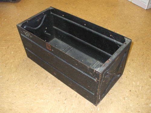
A WWII-era wrinkle-finish black equipment case rescued from the scrap heap.
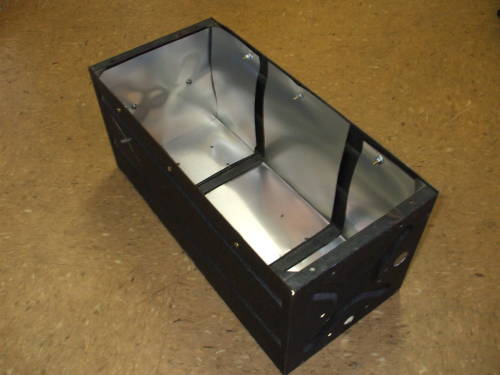
The case gets an inner liner of aluminum flashing.
A roll of thin aluminum flashing provided material with which to form a fairly reflective liner. A few machine screws, all brass to keep with the vintage design theme, hold the flashing in place against the walls of the case.
The light sockets will be mounted to the bottom surface, fastening through the flashing. The remaining narrow black strips are due to shallow internal ribs.
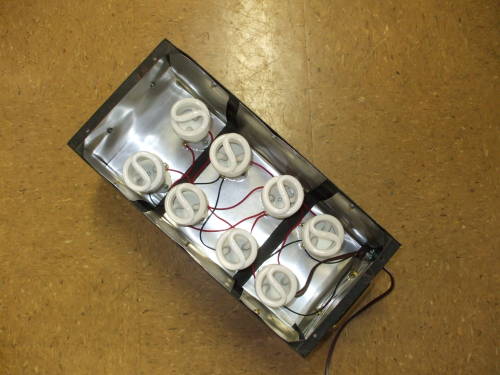
Eight sockets for CFLs.
Eight sockets for CFLs. The small switch above the power cord selects between all eight and diagonally distributed four.
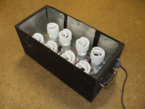
I installed eight sockets. I tried to use CFLs, Compact Fluorescent Lamps, but they just didn't work.
I also added handles, brass of course, so the box could be more easily, well, handled.
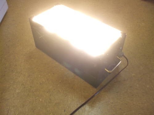
The light box at full brightness.
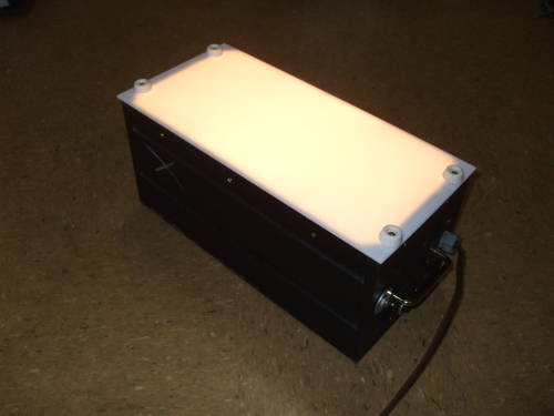
The final design with its "sign white" acrylic face and rubber bumpers.
Why didn't the CFLs work?
The light box needs to be dimmable. So-called "dimmable CFLs" just aren't dimmable in any useful way.
Mark a standard SCR (silicon controlled rectifier) dimmer unit's knob, and you will see that its full range of motion is about 315°. That is, about 7/8 of a complete rotation. If you consider that range of rotation to be 0 through 100% of full power, incandescent bulbs function down to about 5%.
That's full power, not full voltage, as SCR dimmers work sort of as pulse-width modulation devices. The peak voltage out of an SCR is always the full peak line voltage. The SCR dims a lamp by thresholding the voltage somewhere between 0 and 100% of the peak of the input sinusoidal voltage, and only passing that part of the sinusoid greater than that voltage.
Anyway, electrical lesson aside, incandescent lamps dim down to a very small fraction of full brightness before the SCR cuts off completely. "Dimmable" CFLs only dim smoothly to what I would perceive as maybe 80% of full brightness. At that point they enter a state of seizure-inducing flicker, and then drop completely out by maybe 70% of full brightness.
Another difficulty was caused by the nature of the scanning problem.
There is quite a bit of variation in the density (that is, the darkness) of the X-ray films. Some are quite dark. As discussed in detail on a later page in this sequence, the films cannot be removed from the plastic sleeves, and it is not practical to fully mask off the transparent background.
To get the very best images, all of the scanner's surface outside the film itself should be blocked by opaque material. The only light the scanner should see is that which comes through the film.
As the scanner sees more of the full intensity background instead of what is passing through the films, automatic gain control (or AGC) attempts to adjust the sensor sensitivity to produce an output signal with a reasonable amount of variation.
The problem is that some films are very dark. You increase the light level, and the AGC pushes the amplifier gain even further. I eventually realized that an increase in light leads to images with almost no meaningful variation in brightness. The X-ray film appears to be almost entirely black or nearly so, and the background is entirely white. The brighter the background light, the more the image becomes a completely white background with small completely black rectangles corresponding to the films.
I gave up on the "dimmable" CFLs and tried using fixed CFLs. I could use the switch to select between 8 and 4 lamps, and individually unscrew bulbs to modulate the light level in steps.
I eventually went to "100-watt equivalent" CFLs, CFLs that claim to have the same light intensity as 100-watt incandescents. I remain convinced that the CFLs had nowhere near the claimed light output, even after giving them several minutes to warm up. With 8 CFLs in an array it was obvious that not all came on simultaneously, and once they were all on, there was quite a bit of variation in brightness between individual bulbs for several minutes.
What my box was tending toward.
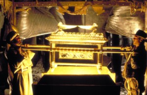
Meanwhile my background got brighter and brighter, until the box was looking like when the Nazis opened the Ark of the Covenant toward the end of Raiders of the Lost Ark.
Some careful measurements, including calculating image brightness histograms and attempting to enhance the images with both global and localized histogram equalization showed the folly of the higher light intensities.
After using the local Menards home improvement center like a lending library of lightbulbs, I finally settled on an array of eight 25-watt incandescents. That puts the "sweet spot" of useful dimmer settings in the range of 40-75% of full, giving me the range I need without too much touchiness on the control.
A local plastics supplier was a source for 1/8 inch (3 mm) acrylic sheet they refer to as "sign white". It's the material used to make marquees and other back-lit signs.
That was cut to size, and some #10-32 self-tapping machine screws pass through rubber feet and holes in the acrylic sheet to thread into the end lips of the CS-48 case.
When you are drilling acrylic sheet or similar plastic, make sure to use a dulled drill bit, or at least one with a decreased lip angle! Normal bits will aggressively bite into the plastic and pull themselves in too quickly, splitting the work material.
I also put together a simple SCR-dimmed outlet box — a rotary dimmer and a duplex outlet in a 2-gang electrical box.
Now you're finally ready to consider The nature of the X-ray films