Network and Telecommunication Cables
Cables, cables, cables!
High-speed serial, Ethernet, Fiber, DS3, OC3, and even telco punchdown cables. Here is how to make sense of data communication cables used for raw device-to-device connections and also for running TCP/IP network protocols.
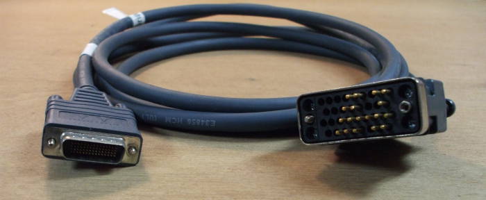
First, the fundamentals: Below is an ANSI/TIA/EIA-422-B (formerly RS-422) or ITU-T V.35 serial cable for connecting a Cisco router's serial port to a T1/DS1 interface.
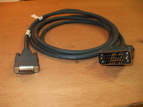
The V.35 interface is now specified as ITU-U V.11. V.35/V.11 is for data communication at speeds up to 10 Mbps.
This type of cable has a DB-60 connector at the router end, and a Winchester block connector at the network interface end. Cisco's description including pinouts is here.
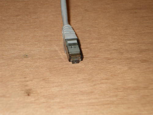
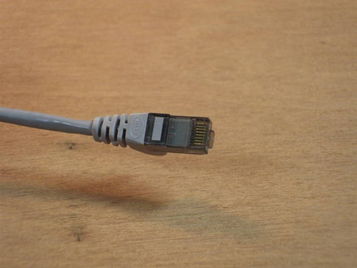
RJ-45 connector (informally), right to left are pins 1 to 8.
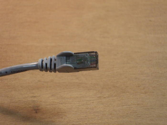
Here is one end of a Category 6 Ethernet cable, or more formally, ANSI/TIA/EIA-568-C.1. The connector is informally known as an RJ45. To be pedantic, it is really an 8P8C modular connector.
Why is "RJ45" incorrect? The RJ45 standard refers to the physical connector and the wiring pattern. A true RJ45 was used for an analog telephone connection and was intended for use with a high-speed modem. Pins 5 and 4 were the tip and ring, respectively, of a single telephone line, and pins 7 and 8 were a programming resistor.
The wiring of a true 8P8C connector is:
| Pin | EIA T568A | EIA T568B | ||
| Wire, of pair | Color | Wire, of pair | Color | |
| 1 | 1 of 3 | white/green | 1 of 2 | white/orange |
| 2 | 2 of 3 | green | 2 of 2 | orange |
| 3 | 1 of 2 | white/orange | 1 of 3 | white/green |
| 4 | 2 of 1 | blue | 2 of 1 | blue |
| 5 | 1 of 1 | white/blue | 1 of 1 | white/blue |
| 6 | 2 of 2 | orange | 2 of 3 | green |
| 7 | 1 of 4 | white/brown | 1 of 4 | white/brown |
| 8 | 2 of 4 | brown | 2 of 4 | brown |
| To make a crossover cable, wire one end as T568A and the other as T568B. | ||||
10BASE-T (Ethernet) and 100BASE-TX (Fast Ethernet) use wire pairs 2 and 3, or wires 1/2 and 3/6.
10BASE-T uses two differential voltages: +2.5V or -2.5V, signalling at 10 Mbaud.
100BASE-TX uses three differential voltages: +1V, 0V or -1V. 4B5B binary encoding generates a signal clocked at a 125 MHz symbol rate. Data bits are grouped into groups of 4 bits each, each data block converted to a 5-bit block guaranteed to have at least two transistions and solve problems of receiver clock synchronization, DC equalization, and spectrum shaping.
1000BASE-T (Gigabit Ethernet) uses all four wire pairs, signaling with 5-level pulse amplitude modulation at a 125 Mbaud symbol rate.
| Category | Bandwidth |
| 3 | 16 MHz |
| 4 | 20 MHz |
| 5, 5e | 100 MHz |
| 6 | 250 MHz |
| 6a | 500 MHz |
| 7 | 600 MHz |
| 7a | 1000 MHz |
| Electrical characteristics for Cat.5e | |
| Property | Value |
| Impedance at 100 MHz | 100±15Ω |
| Capacitance at 800 Hz | 52 pF/m |
| Inductance | 525 nH/m |
| DC resistance | ≤0.188Ω/m |
| Propagation speed | 0.64c |
| Propagation delay | 4.8-5.3 ns/m |
All these standards should be able to communicate over cables up to 100 meters long. Cables are rated in terms of their RF bandwidth rather than supported bit rate, as listed in the table at right.
The wire pairs are twisted together to create a bundle of balanced transmission lines and reduce crosstalk between pairs. The twisting is at 1.5-2 cm per turn.
The wires are #24 AWG or 0.205 mm², rated for 0.577 A maximum current.
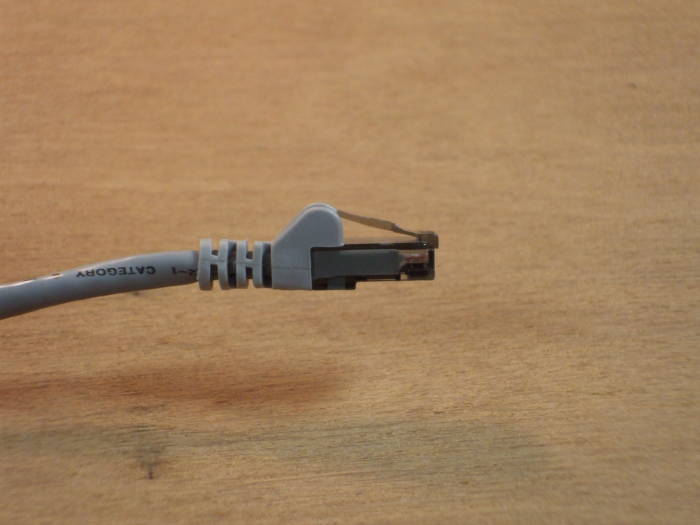
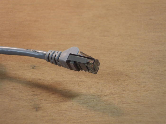
8P8C connector, pins 1 through 8 from top to bottom.
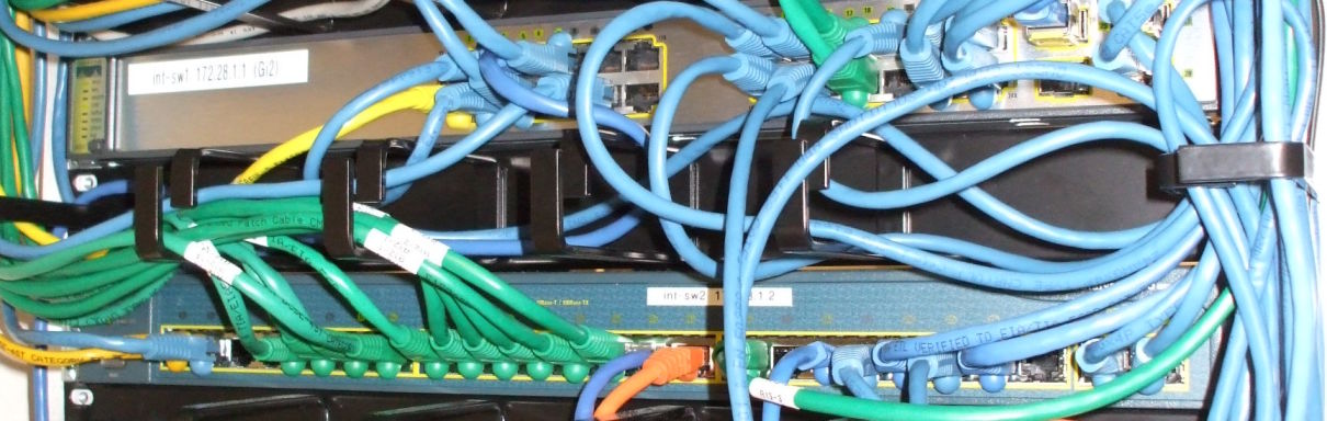
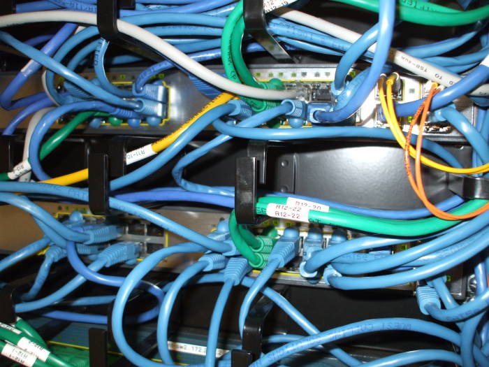
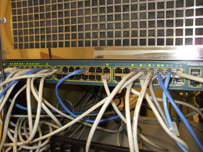
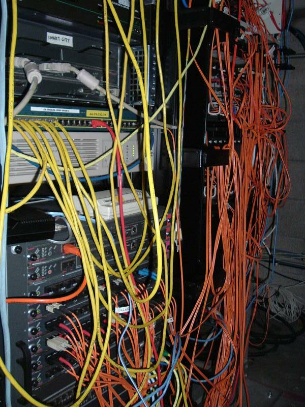
The blue and green cables here are Category 6 Ethernet cables plugging into a bank of Cisco switches, along with four fiber optic lines (smaller diameter yellow and orange lines).
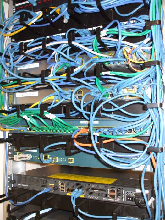
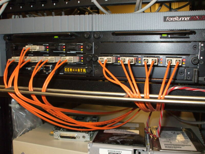
Above are fiber optic network connections.
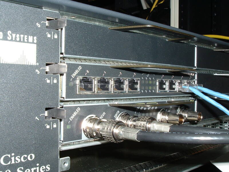
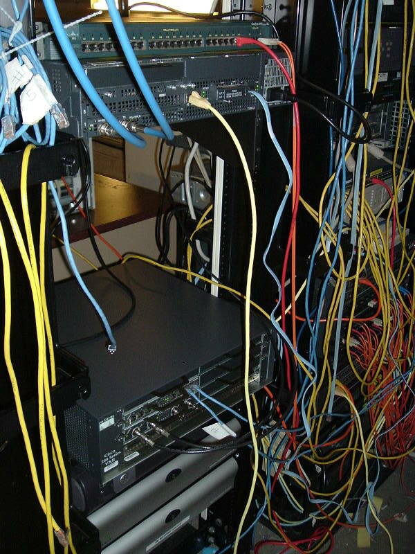
Below are, first, ANSI/TIA/EIA-422-B serial connections to three Cisco routers.
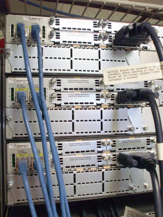
Then, a Fujitsu FLM 600 MD / 2400 LS OC-12 SONET ring and FLM-150 SONET interfaces.
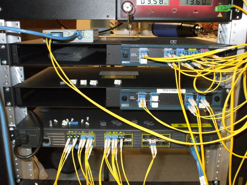
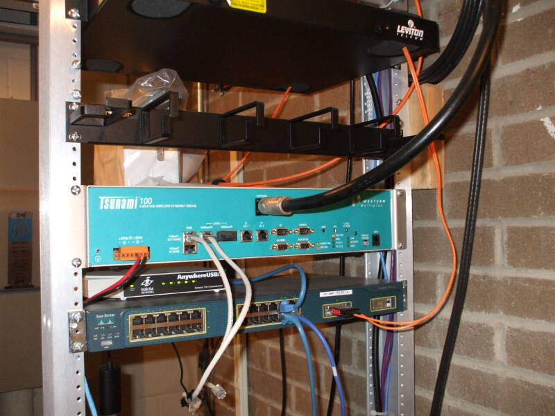
This is a Tsunami 100 5.3/5.8 GHz wireless Ethernet bridge mounted above a Cisco Catalyst 2950 switch with 24 Ethernet ports and two fiber ports.
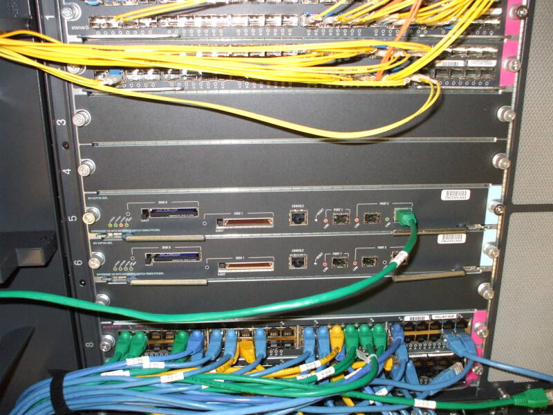
Below is an ATM switch...
...and a Cisco Catalyst 48-port Ethernet switch.
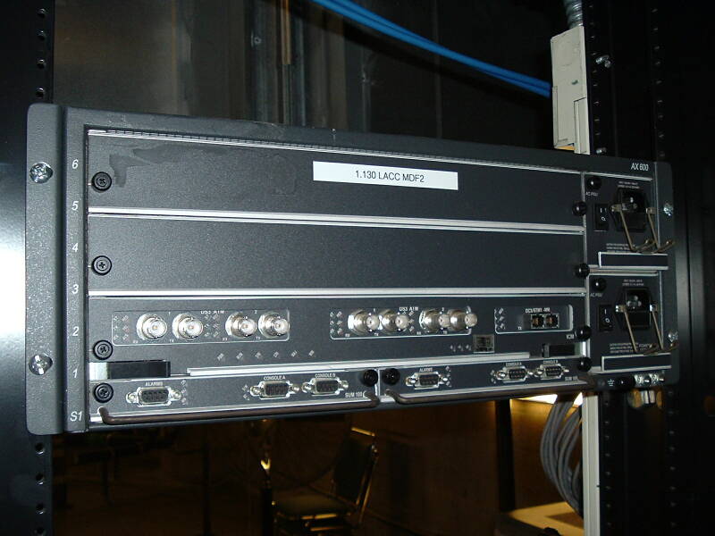
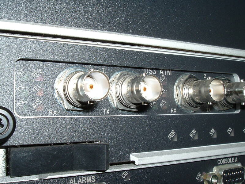
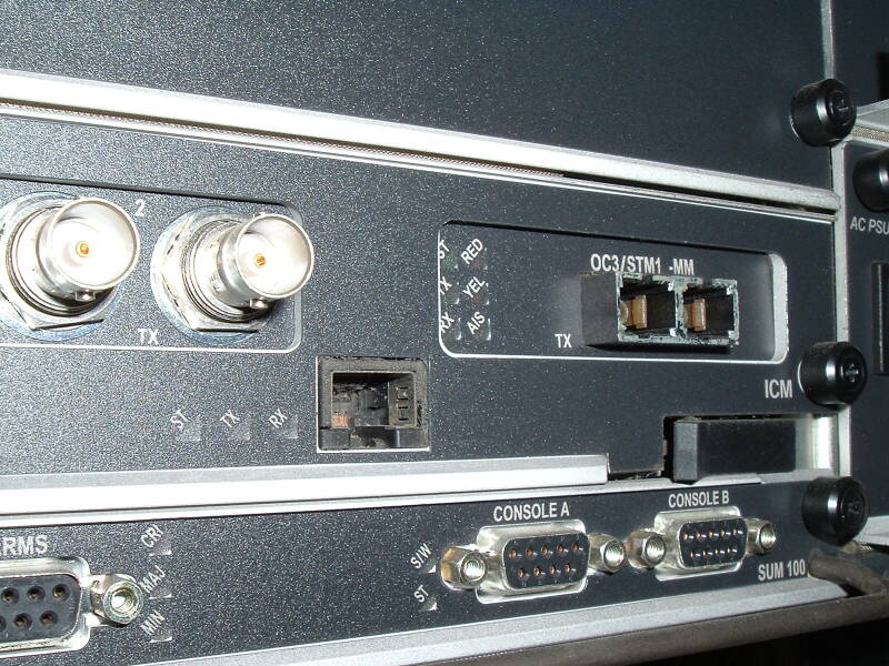
Below are DS3 and OC3 router interfaces on a Lucent Packetstar AX 600 and a Cisco 7204.
Installation
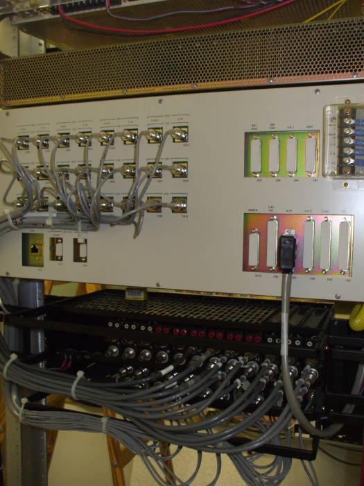
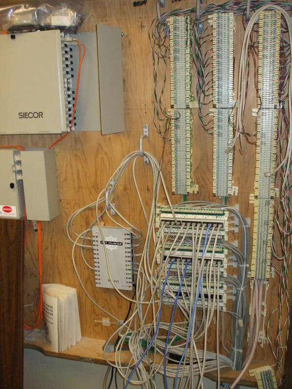
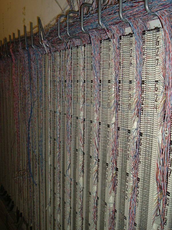
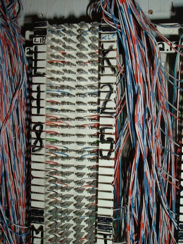
Here are some telecommunications punchdown blocks. The first panel is relatively simple and widely spaced as these things go.
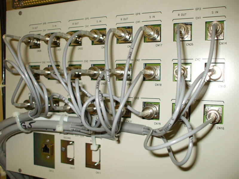
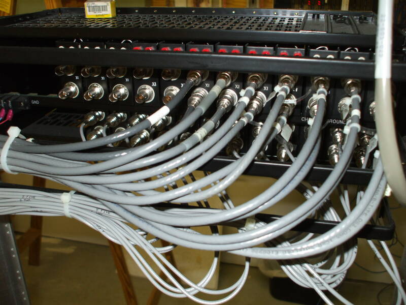
The large panel shown overall and in detail below is at a major conference center.
Finally, here is a random collection of dangling Ethernet and fiber lines:
If you like this, make sure to see my page showing the telecommunications infrastructure in Manhattan.