Driving the Ring Road Around Iceland
Long Waves Need Large Antennas
I was driving counter-clockwise around the
Reykjanes peninsula,
following the south coast.
Before long I was approaching
Grindavík.
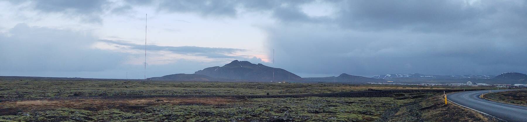
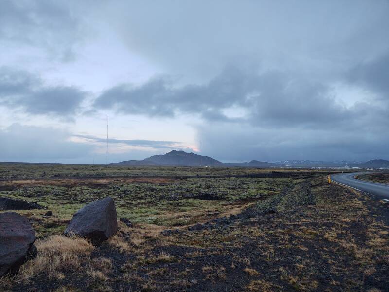
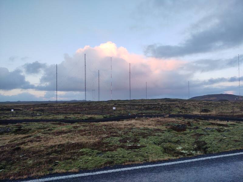
That's Mount Þorbjörn
in the distance below, with the town of
Grindavík to the right.
In front of Þorbjörn is the
Naval Radio Transmitter Facility
Grindavík.
The last 30 U.S. military personnel left Keflavík
in 2006, but this U.S. Navy communication facility remains.
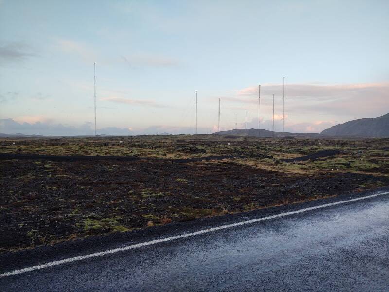
The two tall guyed masts are 600 feet and 1000 feet tall. They're used for low-frequency communication. The station operates at 37.5 kHz with callsign TFK, sending data in one to four 50 baud MSK channels.

A 1000-foot mast sounds like a very large antenna. But electrically it is extremely short for a signal at that very low frequency, thus very long wavelength. The speed of light is almost exactly 300 million meters per second. So, a signal at 37.5 kHz has a wavelength of 8,000 meters.
If you want to make an antenna that sticks up from the ground like this, ideally it would be a quarter-wave vertical antenna. However, that would have to be a quarter of 8,000 meters, or 2,000 meters tall.
A 1,000 foot mast is a valiant effort, but a full quarter-wave at 37.5 kHz would be 6,562 feet, well over a mile tall. And if you ask "Why not use another type of antenna?", the alternative is far worse. The benefit of a quarter-wave vertical is that it's effectively just half of an antenna, sticking up from ground level. Your next choice is something that's a half-wavelength long, twice as large, placed at least one full wavelength above ground. Yes, something 4 kilometers across suspended 8 kilometers above the ground.
So you put up as tall a mast as your resources allow, and the U.S. Navy's resources allow for it to be pretty tall.
Matching an end-fed HF antennaYou would prefer an antenna with a purely resistive 50 Ω impedance. As the antenna shortens, the resistive component drops toward zero and a capacitive reactance begins to climb. With these gigantic masts still being extremely short compared to the long wavelength, something has to be done.
To make a physical analogy, an impedance mismatch is like starting your car engine, then placing the transmission into the highest gear to start moving. As you slowly gain speed, you switch the transmission to lower gears, going to lower and lower gears as you reach higher speeds.
You would rightfully complain that that's an inappropriate way to drive an automobile. It's hard on the engine, hard on the transmission, and you will waste a lot of fuel until you destroy either the engine or transmission. An impedance mismatch is very much like that, but with radio-frequency voltages and currents instead of gears.
See the page further into the trip showing HF antennas at lighthouses in the Eastfjords region. Those HF systems use much shorter wavelengths, making a "capacitance hat" practical.
A theory-but-not-practice solution would be to add what's informally called a "capacitance hat" to the far end of the antenna. But that would mean an enormous umbrella-like structure extending out from the top of that 1,000-foot mast!
You don't "tune" an antenna. It remains what it is, physically and electrically. In this case it's a 305-meter thin steel rod standing vertically on a very sturdy insulator. What you do is build a matching network of reactive elements, inductors and/or capacitors, at the feed point.
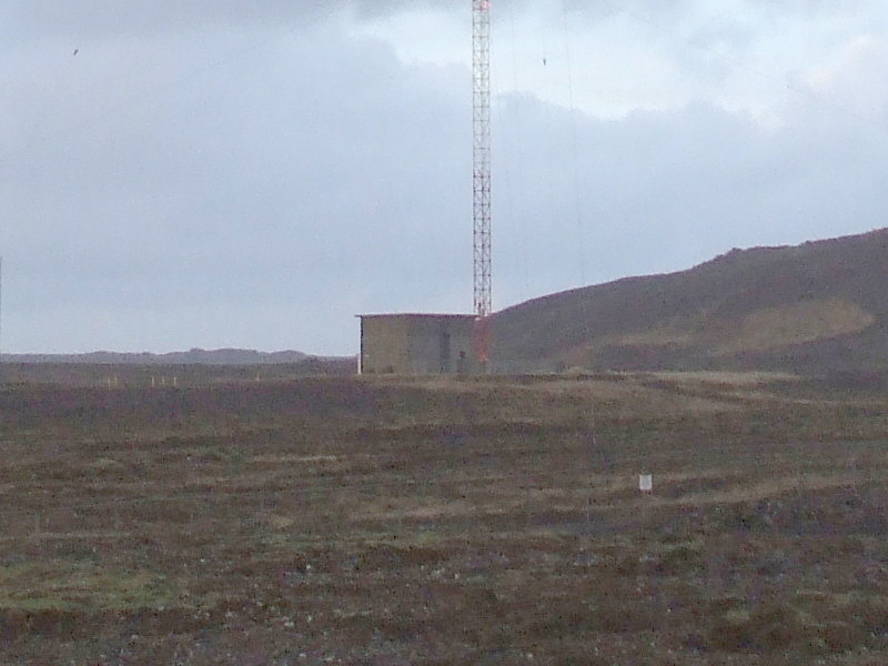
You build that radio-frequency circuit in a "matching shack" at the base, because the circuit needed at these low frequencies will be physically large. Or maybe you call it a "helix hut" because an electrically very short antenna is going to need a lot of inductance, meaning large spring-like coils, to make the total impedance reasonably close to the purely resistive 50 Ω you would like to achieve.
Couple all that inductance with the high power a station like this will need to run, likely 100 to 1,000 kilowatts, and you get very high voltages, arcing, and a fire that burns down the matching shack.
Eventually they got the bugs worked out. Here's the current matching shack.
Discussion of all this becomes more confusing because a lot of radio technology got locked in place during "the golden age of wireless". That was way back when they called it "wireless" instead of "radio". Terms like "shortwave", "longwave", "high frequency", "low frequency", and so on, were created in the 1910s and 1920s. So-called "high frequency" signals at 3 to 30 MHz are at ridiculously low frequencies compared to those used by systems like WiFi and mobile phones.
The outdated terminology we're stuck with includes:
| Names | Frequency | Wavelength |
| Very Low Frequency (VLF) | 3–30 kHz | 10,000–100,000 meters |
| Longwave (LW), Low Frequency (LF) | 30–300 kHz | 1,000–10,000 meters |
| Medium-Wave (MW) | 300–3,000 kHz | 100–1,000 meters |
| Short-Wave (SW), High Frequency (HF) | 3–30 MHz | 10–100 meters |
| Very High Frequency (VHF) | 30–300 MHz | 1–10 meters |
| Ultra High Frequency (UHF) | 300–3,000 MHz | 0.1–1 meters |
Compare that to WiFi signals at 2.3 and 5.5 GHz, with wavelengths around 13 and 5.5 centimeters, respectively, and to the millimeter-wave systems already in use. For example, the "Freedom Peep" mm-wave backscatter systems used at U.S. airports to see through your clothing.
So if long-wave signals are such a hassle to use, why bother?
RadioPropagation
Very-low-frequency (VLF) or long-wave signals tend to travel along the surface of the Earth. It's what's called "ground-wave propagation". In the right circumstances it can yield much greater range than the relatively higher frequency of, say, the AM or medium-wave broadcast band at 530–1700 kHz.
Long-distance communication with points on or near the surface of the Earth, well beyond the horizon — that is of great interest to a Navy. GlobalSecurity.org says that NRTF Grindavík is involved in the Integrated Submarine Automated Broadcast Processing System or ISABPS, so they want signals propagating at the surface or even slightly below. The lower the frequency, the better it penetrates seawater.
The lowest radio frequencies like this work far better when the entire path is in darkness. Better yet, when it has been in darkness for a long enough period for the lower-altitude ionization caused by solar radiation to have dissipated. So, a navy would like to place their transmitter far to the north, to communicate with vessels similarly far to the north.
And so, long-wave broadcasting is also useful to countries at high latitudes. Car radios in Europe often include the longwave broadcasting band. Iceland's national broadcaster RÚV has two broadcast channels. Rás 1 and Rás 2. Both broadcast on the FM and AM bands, and also on longwave at 189 kHz and 207 kHz. The broadcast on 189 kHz, the lower frequency and thus the longer wavelength, uses a 412-meter guyed mast, the tallest in Europe. Iceland's fishing fleet can listen to the radio from home when they're far out over the horizon, much too far away to pick up signals on the AM or medium-wave band.
So how does a fishing ship receive longwave signals? Wouldn't it need a gigantic antenna?
No, you make a longwave receiving antenna with several turns of thin wire around a coil one to a few meters in diameter. Or, wound around a rod of ferrite material.
So why don't you use that design for the transmitter antenna?
You want to run tens to hundreds of kilowatts of 30–50 kHz electrical power into a small multi-turn coil? You have just built a Tesla coil. Enjoy the brief light show as everything in the vicinity of your coil is enveloped in plasma.
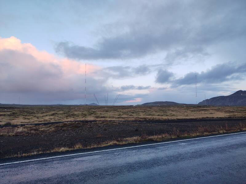
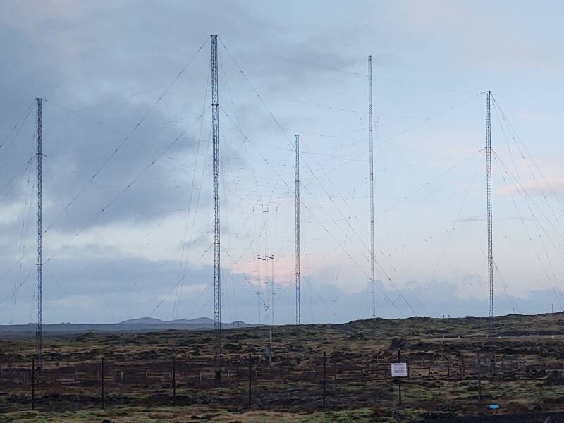
The Grindavík facility also has some complicated antenna structures formed from rectilinear webs of wire suspended between four masts.
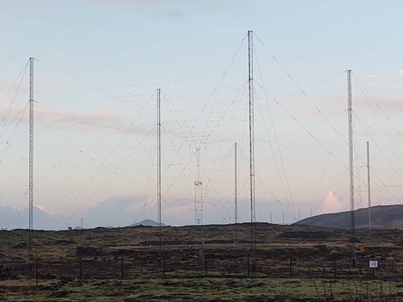
By switching the feedline connections with an array of relays at the base, this provides directional beam antennas across a wide range of HF (3–30 MHz) frequencies.
According to navy-radio.com, in the early 1970s the Grindavík site's HF transmitters included several AN-FRT-39 (10 kW) and FRT-40 (40 kW) transmitters. The VLF systems used an AN/FRT-19 (15 kW) and an AN/FRT-72.
Now, to return all the way back down to 50 Hz electrical power, let's rejoin the tour at Grindavík.
as in this;
Þ/þ is unvoiced,
as in thick.